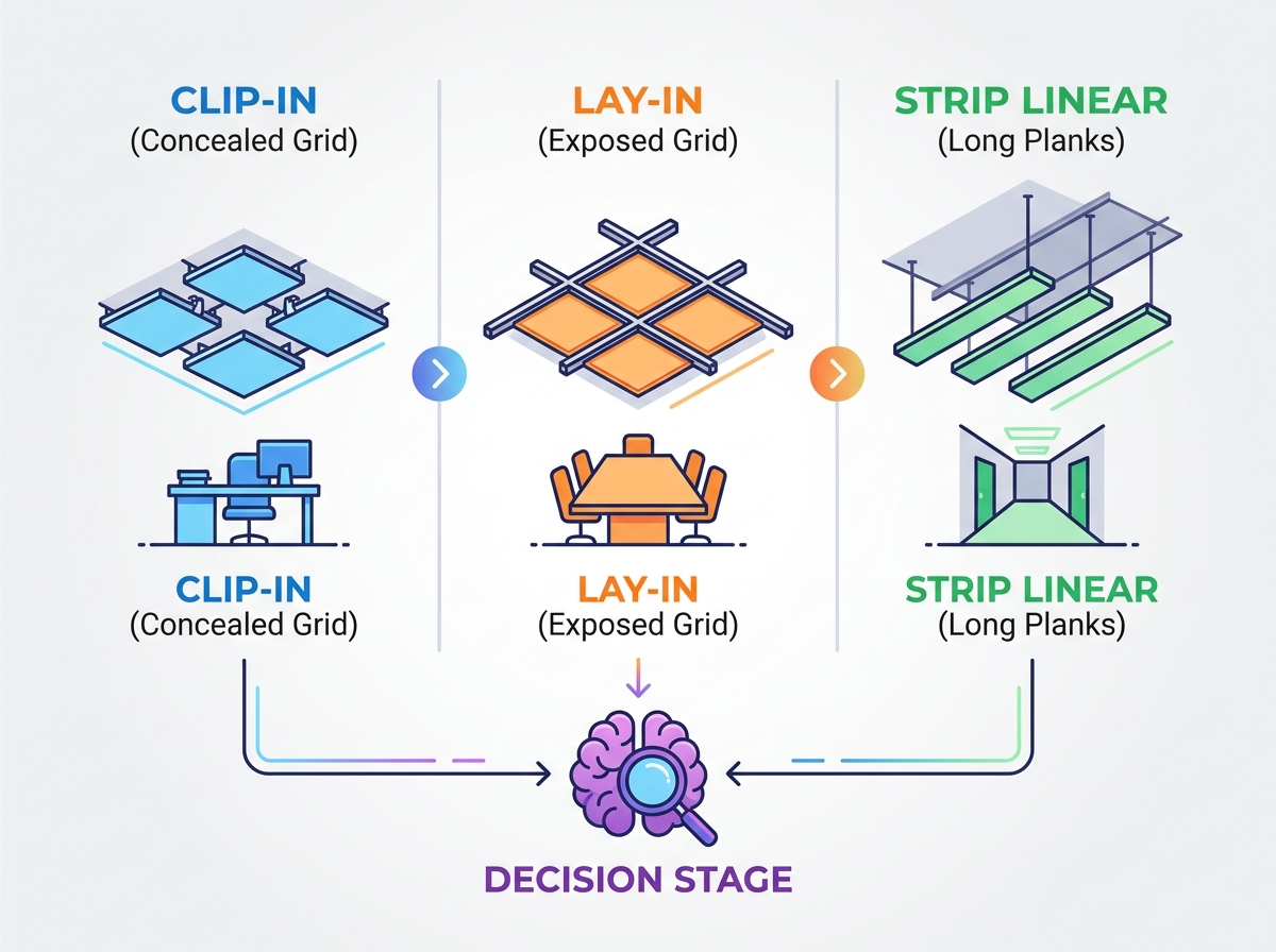
Commercial and institutional architecture demands ceiling systems that deliver uncompromising durability, precise acoustic control, and seamless integration with overhead utilities. Specifying the wrong suspension or panel type causes major structural and operational issues. Restricted plenum access, compromised hygiene standards, structural misalignment, and inflated labor costs often plague poorly planned projects. You must align architectural intent with operational realities. We evaluate the three primary configurations—clip-in, lay-in, and strip linear—to match structural requirements with the right ceiling system. Field conditions dictate that suspension grids must support heavy mechanical loads while allowing maintenance crews to work efficiently. Selecting the correct metal profile prevents sagging, mitigates wind uplift, and ensures compliance with strict fire codes. This technical breakdown provides the exact specifications needed to execute flawless overhead installations across diverse commercial environments.
Clip-in systems utilize a concealed grid to provide a secure, monolithic finish ideal for high-hygiene environments like hospitals and cleanrooms, though they require specialized tools for plenum access.
Lay-in systems rest on an exposed T-grid, offering the most cost-effective installation and rapid, tool-free access to HVAC and electrical systems in standard commercial spaces.
Strip linear systems deliver directional aesthetics and high versatility for both interior corridors and exterior soffits, requiring precise carrier alignment and wind-uplift mitigation.
Baseline Success Criteria for Specifying an Aluminum Ceiling
Problem Framing
You must define operational parameters before selecting a panel profile. Ask yourself how often maintenance crews need plenum access. Determine your aesthetic goals early in the design phase. A solid aluminum ceiling specification hinges on these initial decisions. Failing to map out these requirements leads to incompatible system choices. You risk installing a permanent-looking ceiling in a space that requires weekly overhead maintenance. We see this constantly on job sites where architects specify concealed grids in IT server rooms. The result is damaged panels within the first month. You must verify the available plenum depth. Lay-in systems require at least 4 to 6 inches of clearance above the grid to angle the panels during insertion. Clip-in systems can operate with tighter clearances since panels push straight up into the spring tee.
Material Quality and Pre-Installation Inspection
Establish strict quality control protocols upon delivery. Panel surfaces must arrive entirely free of cracks and scratches. Verify the precision of interlocking edges immediately. Check tongue and groove joints or carrier clips before deployment. Reject damaged batches immediately to prevent installation delays. Installers must wear clean cotton gloves during handling. This prevents oil transfer and protects the factory finish. Inspect the metal gauge thickness to ensure it matches your structural requirements. Standard commercial applications require at least 0.6mm thickness to prevent warping under their own weight. Heavier gauges are necessary for large-format panels to maintain a perfectly flat visual plane.
Acoustic and Thermal Performance
Bare metal reflects sound heavily. You often need acoustic fleece backing or micro-perforations to mitigate this issue. These additions help achieve target Noise Reduction Coefficient (NRC) ratings. Highly reflective environments demand these acoustic upgrades. Standard perforated panels typically achieve an NRC of 0.70 to 0.90 when paired with the correct acoustic inlay. You must specify the perforation pattern based on both acoustic needs and visual preference. We recommend a 20% open area perforation for spaces with heavy foot traffic and hard flooring. Thermal performance also matters in top-floor installations. You can lay fiberglass batt insulation directly over the metal panels to prevent heat loss, provided the suspension grid is engineered to carry the additional dead load.
Fire Ratings and Code Compliance
Verify local building code compliance before ordering materials. Ensure the selected alloy, panel thickness, and powder-coated finish meet strict non-combustibility requirements. Look for ASTM E84 Class A flame spread ratings. Commercial spaces require materials that do not contribute to fire propagation. The suspension grid must also meet seismic code requirements in active fault zones. Specify heavy-duty grid components where seismic activity poses a risk. Use 12-gauge hanger wire tied with three tight wraps to secure the main runners to the roof deck. Install seismic splay wires at 45-degree angles to prevent lateral movement during an earthquake.
Maintenance and Plenum Accessibility
Map the frequency of overhead MEP (Mechanical, Electrical, and Plumbing) access against panel removal ease. High-access areas require different systems than secure, sealed zones. Data centers need constant access to cable trays. Cleanrooms require sealed plenums to maintain positive air pressure. Match the ceiling system to the maintenance schedule of the facility. Ignoring this metric guarantees future operational headaches. Consider the location of VAV boxes, fire dampers, and plumbing cleanouts. Ensure the ceiling system directly below these utilities allows for rapid, non-destructive entry.
Evaluating the Clip-In Aluminum Ceiling System
Structural Mechanics
This system relies on a robust concealed suspension grid. Installers push panels upward until they snap securely into a spring tee runner. This creates a flush, seamless surface. The grid remains completely hidden from below. The spring tee applies continuous pressure to the panel edges. This pressure keeps the panels perfectly aligned and prevents sagging. You can specify square edges for a monolithic look or beveled edges for a subtle grid pattern. The spring tees lock into primary channels suspended by threaded rods or galvanized wire. The entire framework creates a rigid, interlocking plane that resists movement.
Ideal Use Cases
Specify a clip-in aluminum ceiling for cleanrooms, commercial kitchens, and healthcare facilities. High-security areas also benefit immensely from this configuration. These environments require a washable, airtight seal. They also demand restricted plenum access to prevent unauthorized entry. Psychiatric wards and correctional facilities use heavy-gauge clip-in systems to prevent tampering. Food processing plants rely on them to withstand high-pressure washdowns. The concealed grid prevents moisture from penetrating the plenum space, protecting the structural deck above.
Performance Advantages
The system offers exceptional resistance to upward pressure. Drafts and aggressive cleaning will not dislodge the panels. The monolithic aesthetic eliminates visible grid lines entirely. It provides a clean, uninterrupted visual plane. The tight joints prevent dust and bacteria accumulation. This makes the system inherently hygienic. You can easily integrate flush-mounted LED lighting and HEPA filters into the grid layout. Silicone sealants applied to the panel edges create a completely sterile barrier for operating rooms and pharmaceutical manufacturing areas.
Conceptual Trade-offs
Initial installation runs slower compared to drop-in alternatives. Every panel requires precise alignment before engaging the spring tee. Maintenance crews need specialized extraction tools to remove panels. Prying panels without these tools damages the metal edges permanently. Expect higher upfront labor costs during the build phase. You must train facility managers on the correct panel removal techniques to avoid long-term damage. The tight clearances make it difficult to route new large-diameter ductwork after the ceiling is fully installed.
Installation Execution Steps
Establish the ceiling elevation using a rotary laser level across the entire room perimeter.
Secure the perimeter wall angle using appropriate masonry or drywall anchors every 16 inches.
Install the primary suspension channels at 48-inch centers using 12-gauge hanger wire.
Attach the spring tee runners perpendicular to the primary channels at 24-inch centers.
Snap the metal panels into the spring tees, starting from the center of the room and working outward.
Cut the perimeter panels to size using aviation snips and secure them into the wall angle with hold-down clips.
Evaluating the Lay-In Aluminum Ceiling System
Structural Mechanics
These panels drop directly into a standard 15mm or 24mm exposed T-grid suspension system. Gravity holds the panels securely in place. The grid flanges support the panel edges along all four sides. You can choose between tegular (drop) edges or square edges. Tegular edges allow the panel to hang slightly below the grid. This creates a three-dimensional architectural shadow line. Square edges sit completely flush with the T-bar. The main runners and cross tees interlock to form a rigid modular framework. The grid components feature factory-punched holes for hanger wire attachment.
Ideal Use Cases
Corporate offices, retail environments, and educational facilities rely heavily on this setup. Data centers also use them extensively. These spaces require continuous, unhindered access to overhead cabling and ductwork. IT technicians need to route new cables frequently. HVAC technicians require immediate access to VAV boxes. A lay-in aluminum ceiling accommodates these fast-paced operational demands perfectly. Retail stores use them to easily relocate lighting fixtures when changing merchandise displays.
Performance Advantages
This system ensures rapid installation and replacement. Facility managers enjoy completely tool-free plenum access. You simply lift and tilt the panel to reach the utilities above. It integrates easily with standard modular lighting and HVAC diffusers. Standard 2x2 or 2x4 fixtures drop right into the same grid. This compatibility simplifies the entire ceiling design process. Damaged panels swap out in seconds without disrupting surrounding units. The exposed grid allows for easy visual inspection of the suspension system over time.
Conceptual Trade-offs
The exposed grid breaks the visual continuity of the ceiling plane. You see the metal T-bars separating each panel. Panels remain susceptible to displacement from sudden air pressure changes. Opening a large door can create a draft that lifts the panels. You must specify rigid hold-down clips in drafty areas to prevent rattling. The exposed grid also collects dust over time, requiring periodic wiping. The thin metal edges of the panels can dent easily if dropped during maintenance operations.
Field Execution Tips
Always square the grid before dropping in the metal panels to prevent uneven reveals.
Use a string line to ensure the main runners remain perfectly straight over long distances.
Install hold-down clips immediately after placing the panels in areas near exterior doors or loading docks.
Coordinate with the MEP trades to ensure ductwork does not interfere with the suspension wires.
Keep a box of spare panels on-site to immediately replace any units damaged during the final construction punch list.
Evaluating the Strip Linear Aluminum Ceiling System
Structural Mechanics
This system features long, narrow aluminum panels. Installers snap them onto a continuous carrier track suspended from the roof deck. You can specify closed or open-reveal configurations. Open reveals allow air and sound to pass through freely. Closed reveals utilize filler strips to create a solid surface. The carrier tracks feature pre-punched prongs. These prongs dictate the exact spacing and module width of the linear strips. The carriers run perpendicular to the panels, providing continuous support along the entire length of the ceiling.
Manufacturing Profiles
Manufacturers offer lightweight roll-formed panels for standard interior applications. These typically range from 0.5mm to 0.7mm in thickness. For demanding environments, specify heavy-duty extruded profiles. Extruded profiles provide superior rigidity and impact resistance. They usually exceed 1.0mm in thickness. Extruded panels span greater distances without sagging. They handle exterior wind loads much better than roll-formed alternatives. The extrusion process allows for sharper corners and deeper profiles, enhancing the architectural shadow lines.
Ideal Use Cases
Use a strip linear aluminum ceiling in airport terminals and long corridors. They work perfectly for exterior overhangs and soffits. Spaces requiring strong directional design lines benefit greatly. You can use them to guide pedestrian traffic visually down a hallway. Custom curved transitions also utilize linear systems effectively. The strips can follow undulating carrier tracks to create wave-like ceiling topographies. Train stations use them to mask heavy structural steel while maintaining an open, airy feel.
Performance Advantages
You gain exceptional design flexibility. The system effectively masks overhead utilities while allowing air circulation in open-reveal formats. This eliminates the need for dedicated return air grilles. The right extruded profiles perform exceptionally well in exterior applications. They resist corrosion and withstand high humidity. You can specify custom lengths to minimize visible end-to-end joints across large spans. The linear aesthetic visually elongates spaces, making narrow corridors feel much larger.
Conceptual Trade-offs
Integrating point-source lighting and safety systems proves complex. You must cut precise openings in the narrow strips for sprinkler heads and downlights. The system requires meticulous carrier leveling over long spans. A slight dip in the carrier track creates a highly visible wave in the finished ceiling. Exterior use demands specific wind-load engineering. You must calculate uplift pressures to prevent panel failure during storms. Replacing a single damaged strip in the middle of a ceiling often requires removing several adjacent panels first.
Exterior Installation Requirements
Verify the local wind load requirements with a structural engineer.
Install heavy-gauge exterior carrier tracks at reduced spacing intervals.
Use rigid threaded rods instead of standard hanger wire to prevent upward movement.
Snap the extruded linear panels onto the carrier prongs and secure them with mechanical fasteners if required by code.
Apply a weather-resistant architectural finish to prevent oxidation from salt air or humidity.
Alternative Configurations: Open Cell and Baffle Ceilings
Expanding the Scope
Clip-in, lay-in, and strip linear systems dominate continuous ceiling planes. However, you must also acknowledge open cell and baffle configurations. These provide distinct functional benefits for specific architectural challenges. They do not form a solid barrier. Instead, they create a porous visual layer. This approach changes how you handle overhead utilities and lighting. You must paint the exposed roof deck and ductwork to ensure they blend into the background.
Strategic Application
Specify these open-plenum alternatives when you need maximum smoke extraction. Fire codes often dictate open ceilings in crowded public venues. They also create dramatic architectural depth. Enhanced acoustic baffling becomes possible without creating a continuous visual barrier. They leave the upper deck exposed while masking the MEP systems. Paint the upper deck black to make the utilities disappear behind the bright metal baffles. This technique is highly effective in modern industrial-style office spaces and large retail showrooms.
Comparative Decision Framework: Features to Outcomes
Installation Speed and Labor Economics
Lay-in grids deploy rapidly. Installers drop panels into place with minimal friction. A standard crew covers massive square footage daily. Clip-in and linear carrier systems require labor-intensive precision. Every clip and carrier notch must align perfectly. You spend more on labor with concealed systems. Budget accordingly during the estimation phase. Factor in the time required to cut linear strips around perimeter walls. Complex room geometries significantly slow down the installation of linear and clip-in systems compared to modular drop-in grids.
Long-Term Durability and Surface Integrity
Assess how each system handles repeated removal. Lay-in panels suffer edge denting if mishandled by maintenance crews. Dropping a panel corners-first bends the thin metal. Clip-in panels risk surface scratching from extraction tools. Train your facility teams to handle the specific system properly. Provide them with the correct manufacturer-approved tools. Implement a stock of attic replacement panels to address inevitable operational damage. Store these spare panels flat in a dry environment to prevent warping over time.
Scalability for Large Commercial Footprints
Massive square-footage deployments require strict supply chain consistency. You must ensure batch color matching across thousands of panels. Decide between powder coating and anodized finishes early. Powder coating offers vast color options. Anodizing provides a harder, metallic finish. Plan for grid expansion joints to accommodate building movement. Long continuous runs of metal expand and contract with temperature fluctuations. Failure to include expansion joints results in buckled panels and warped suspension grids.
Ceiling System Type
Plenum Access Speed
Visual Aesthetic
Primary Use Case
Installation Complexity
Wind Uplift Resistance
Lay-In Grid
Rapid (Tool-free)
Exposed Grid Lines
Offices, Retail, Data Centers
Low
Poor (Requires Clips)
Clip-In Concealed
Slow (Requires Tools)
Monolithic, Seamless
Hospitals, Cleanrooms, Kitchens
High
Excellent
Strip Linear
Moderate
Directional, Slatted
Airports, Corridors, Exterior Soffits
High
High (With Rigid Carriers)
Implementation Risks and Mitigation Strategies
Grid Leveling and Alignment Tolerances
Visible sagging or panel gaps ruin the architectural intent. A poorly leveled grid reflects light unevenly, highlighting every flaw. Mandate laser-leveled suspension drops at manufacturer-specified intervals. Set up a rotary laser level in the center of the room. Mark the perimeter walls and install the wall angle molding first. This establishes your baseline elevation. Never rely on the floor for measurements, as concrete slabs are rarely perfectly level. Use heavy-duty gauge wire to prevent stretch over time. Tie the suspension wires with a strict minimum of three tight wraps. Verify the level of the perimeter wall molding before installing the main runners.
Managing Surface Scratches, Cracks, and Coating Consistency
Material damage happens during transit and installation. Dropped boxes result in bent corners. Sliding panels against each other causes micro-scratches. Specify factory-applied protective films. Remove this film only after final alignment. Conduct rigorous pre-installation inspections for micro-cracks. Enforce strict handling protocols to protect the finish. Store the panels flat in a dry, climate-controlled environment prior to installation. Instruct the electrical trades to use extreme caution when cutting holes for downlights to avoid scratching the surrounding finish.
Environmental Stressors (Wind Uplift & Humidity)
Drafts and moisture compromise ceiling integrity. High humidity causes standard steel grids to rust. Wind uplift dislodges lightweight panels. Specify rigid hold-down clips for lay-in systems in drafty areas near exterior doors. Utilize exterior-grade, corrosion-resistant carriers for strip linear soffits. Ensure all suspension components feature heavy galvanized coatings or aluminum construction in high-moisture environments like natatoriums. Seal the perimeter edges with a high-grade silicone caulk to prevent moisture from migrating into the plenum space.
Conclusion
Consult with a structural engineer to verify the load-bearing capacities of the roof deck before finalizing suspension details.
Request physical panel samples to verify finish, gauge rigidity, and color matching under the actual site lighting conditions.
Review manufacturer warranty terms regarding plenum access frequency and approved cleaning chemicals.
Coordinate with the mechanical and electrical trades to map out all overhead utility penetrations prior to ordering the grid components.
FAQ
Q: What is the main difference between a clip-in and lay-in aluminum ceiling?
A: A clip-in system uses a concealed spring-tee grid. You push panels up to lock them, creating a seamless, secure surface requiring specialized tools for access. A lay-in system uses an exposed T-grid. Panels rest on the flanges via gravity, allowing rapid, tool-free access to the plenum above.
Q: Can a strip linear aluminum ceiling be used outdoors?
A: Yes. Exterior applications require specific wind-load engineering. You must specify heavy-duty extruded profiles rather than standard roll-formed panels. Use exterior-grade, corrosion-resistant carrier tracks and weather-resistant powder-coated finishes to withstand environmental stressors and prevent uplift during high winds.
Q: How do you access the plenum in a clip-in ceiling system?
A: You must use specialized extraction blades provided by the manufacturer. Slide the tool into the microscopic gap between panels to disengage the panel edge from the concealed spring tee. This prevents bending the metal edges or scratching the powder-coated finish during routine removal.
Q: Are aluminum ceilings good for acoustics?
A: Bare metal reflects sound, creating echoes. To achieve high acoustic performance, you must specify micro-perforated panels. These panels are backed with an acoustic non-woven fleece that absorbs sound waves, significantly improving the room's Noise Reduction Coefficient (NRC) and reducing reverberation.
Q: How do you prevent aluminum ceiling panels from rattling?
A: Rattling usually occurs due to HVAC vibrations or sudden air pressure changes. Prevent this by installing rigid hold-down clips on lay-in grids. Ensure proper grid tensioning during installation and use acoustic backing pads to dampen structural vibrations transferred from the roof deck.
Q: What maintenance is required for aluminum ceilings?
A: Maintenance is minimal. Clean the panels using soft microfiber cloths and non-abrasive, neutral detergents to protect the powder-coated or anodized finish from scratches. Conduct regular visual inspections to ensure the suspension grid remains level and structurally sound over time.
Guangzhou Panda Commercial Development Co.,Ltd. is a company based in Guangzhou, China. We have more than 20 years experience in the production and export of wall and ceiling system products.
Address: Unit 1310, 13/F, South Tower of Xijiao Xieli Business Centre,No. 159, Middle of Qiaozhong Road, Liwan District, Guangzhou City, Guangdong Province, China
Subscribe To Our Newsletter
Promotions, new products and sales. Directly to your inbox.